Feature Highlight: Draft — Figure (Illustration)
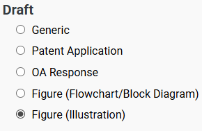
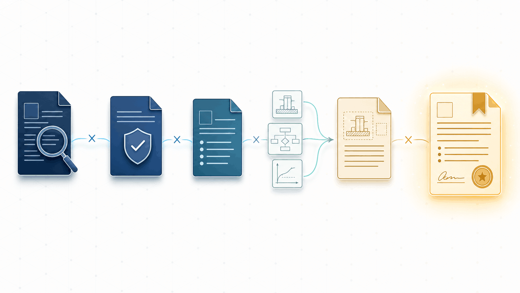
The “Draft — Figure (Illustration)” mode generates patent-style line drawings. It operates in two ways:
- Image-to-line-drawing conversion: You upload a reference image (a photograph, render, or screenshot) and the Sandbox converts it into a clean black-and-white line drawing.
- De novo generation: You describe what you want in text, with no reference image, and the Sandbox generates an illustration from scratch.
Both approaches produce output suitable for use as figures in patent applications. The conversion workflow is more common for mechanical inventions where you already have a photo of the device or prototype. The de novo workflow is useful when you need a conceptual illustration, a simplified schematic view, or a figure depicting something that doesn’t physically exist yet.
The underlying model for this mode was recently upgraded (more on that in the changelog below), and the results are noticeably better in both modes, particularly for complex devices with fine structural detail when converting, and for instruction-following accuracy when generating from text.
The rest of this issue focuses on the image-to-line-drawing conversion workflow. We will cover de novo figure illustration generation in future edition.
Tips & Workflows: Getting the Most Out of Image-to-Line-Drawing Conversion
General Best Practices
1. One image at a time. Provide a single reference image per generation. Feeding in multiple views (different angles, different embodiments) tends to confuse things. If you need multiple views, generate them separately.
2. Let the image do the talking. Don’t over-invest in describing the device in your prompt. A sharp, well-lit, high-resolution photograph will do far more than a paragraph of text trying to describe what the device looks like. A picture is worth a thousand words of prompt, after all. Focus your prompt on how you want the rendering handled, not what the device looks like.
3. Skip the reference numbers. Don’t ask the illustration mode to add reference numerals to the figure. Although it can do this, the numbers are baked into the image. If any reference number needs to change later, you’re either regenerating the entire figure or awkwardly patching over it.
Instead, generate the illustration as a clean image asset and add reference numbers separately. One workflow that works well: upload your finished figure illustration into the “Draft — Figure (Flowchart/Block Diagram)” mode and ask it to generate only the reference numbers, positioned at the approximate locations of the elements they reference. This gives you a Visio file with floating reference numerals that you can overlay onto the illustration PNG. They’ll probably need some repositioning, but it’s faster than placing them all manually from scratch.
4. Divide and conquer. If you’re working with a complex device, consider whether you can convert it in segments. Take a photo of just one portion, get a good line drawing of that portion, then move on to the next. This avoids the frustrating cycle where one small region has an error, forcing you to regenerate the entire figure, only to find a different region now has a problem. If your device lends itself to it, breaking a single complex figure into several more focused illustrations is often the better approach anyway.
5. Iterate by uploading previous attempts. The illustration mode can’t see its own previous outputs. If a generation is almost right but has one or two errors, save that image, upload it as context, and describe what needs to be fixed. This lets you converge on the final result incrementally, rather than hoping a single prompt will get everything right in one shot. You can include or exclude the original reference photo; both approaches work.
An Experiment: How Much Do Resolution and Prompt Matter?
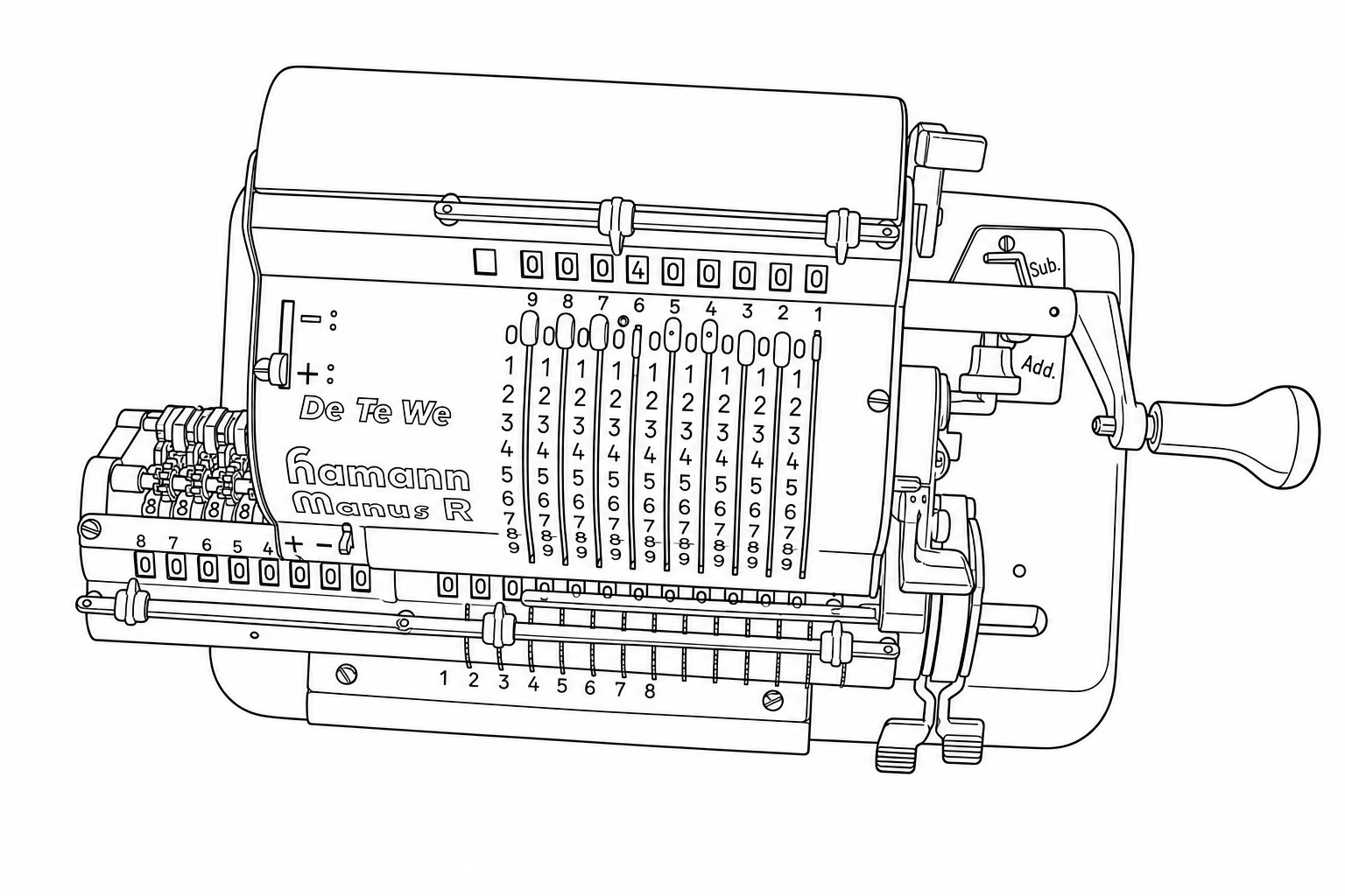
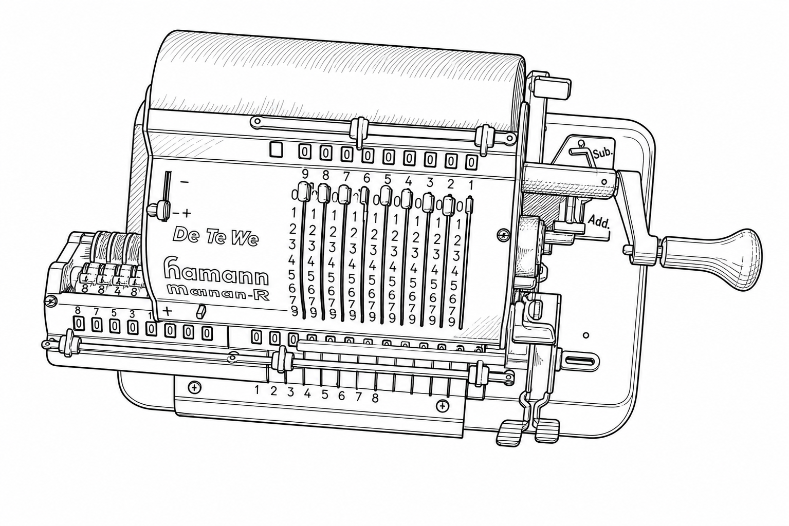
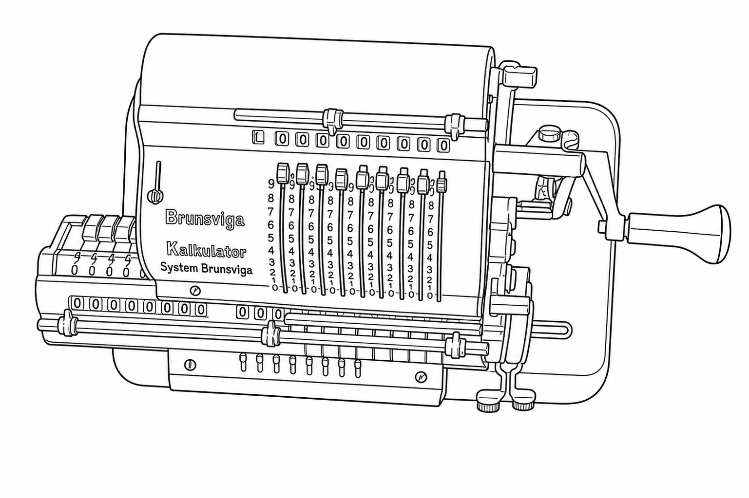
To get a concrete sense of how input quality and prompt wording affect output, I ran a controlled experiment using a photograph of a Hamann Manus R, a mid-century German pinwheel calculator with a lot of fine mechanical detail: sliding levers, numbered drums, a crank handle, various registers, and small text.
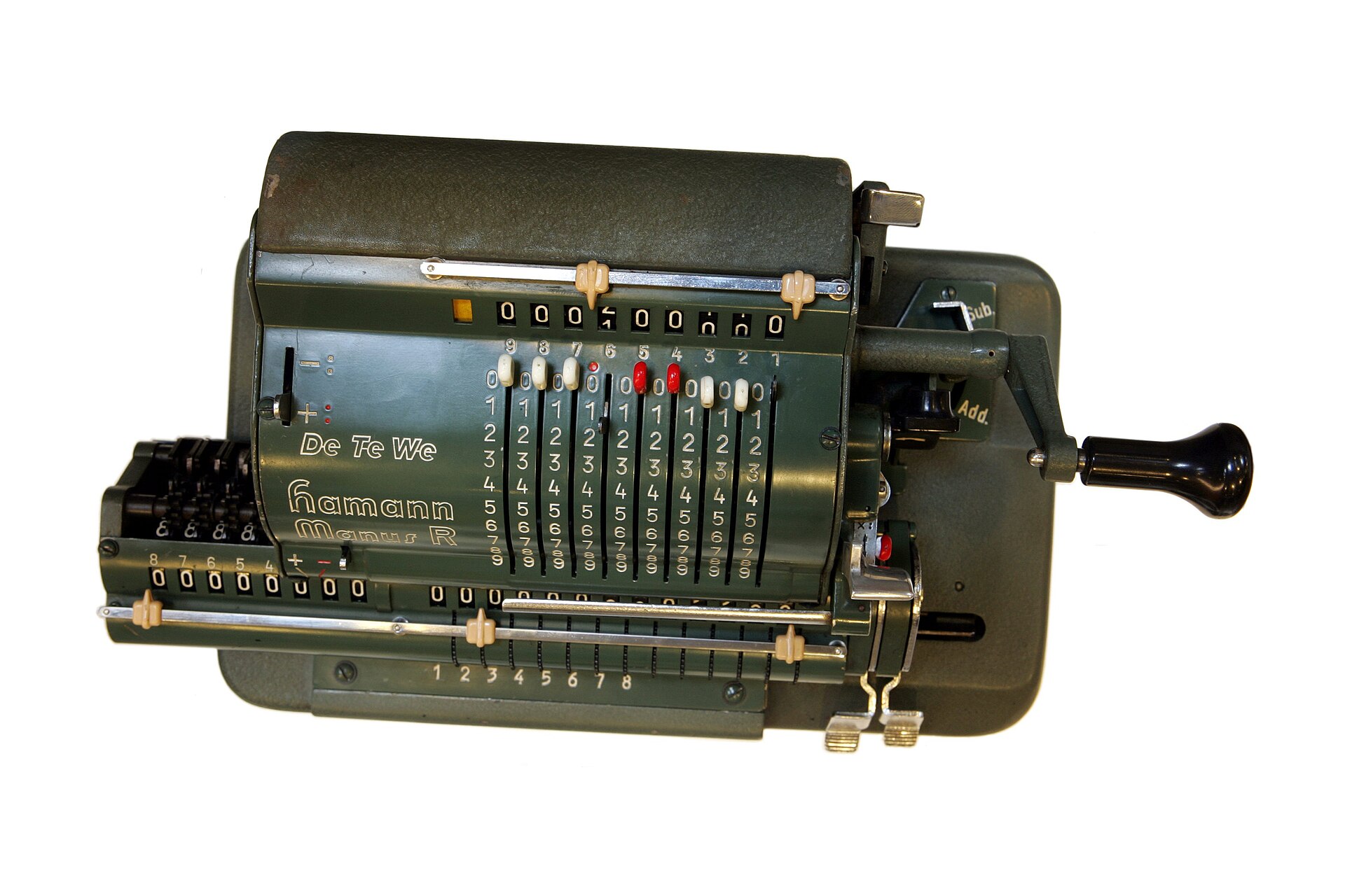
The reference image: a Hamann Manus R mechanical calculator. Nine vertical sliding levers, numbered drums, small text, and various mechanical components partially in shadow. This is the kind of structurally dense subject that stress-tests the illustration mode.
I tested three resolutions of this image:
- High: 1920×1280
- Medium: 1000×667
- Low: 512×341
And three different prompts:
Prompt 1
“Render a line drawing of the provided device EXACTLY as you see it, illustrating all structural features as clean solid black lines, without artifacts. Stay exactly pixel-to-pixel identical to the structural features shown in the provided image, when a feature is hard to see or blurry, do your best to infer the likely structure based on surrounding context.”
Prompt 2
“Convert the provided image into a line drawing.”
Prompt 3
“Generate a line drawing of the device shown in the image, illustrating all structural features using clean solid black lines exactly as shown in the provided image. Ensure the line drawing you generate is suitable for use as a Figure in a US patent application. Ensure the image you generate is completely free of artifacts, noise, or image distortions. Stay exactly pixel-to-pixel identical to the structural features shown in the provided image and do not add or embellish any features, faithfulness to the provided image is of utmost importance.”
Results
Click any image to view it at full size.
| High Res (1920×1280) | Medium Res (1000×667) | Low Res (512×341) | |
|---|---|---|---|
| Prompt 1 |
|
|
|
| Prompt 2 |
|
|
|
| Prompt 3 |
|
|
|
Original Reference
Line Drawing
Takeaways
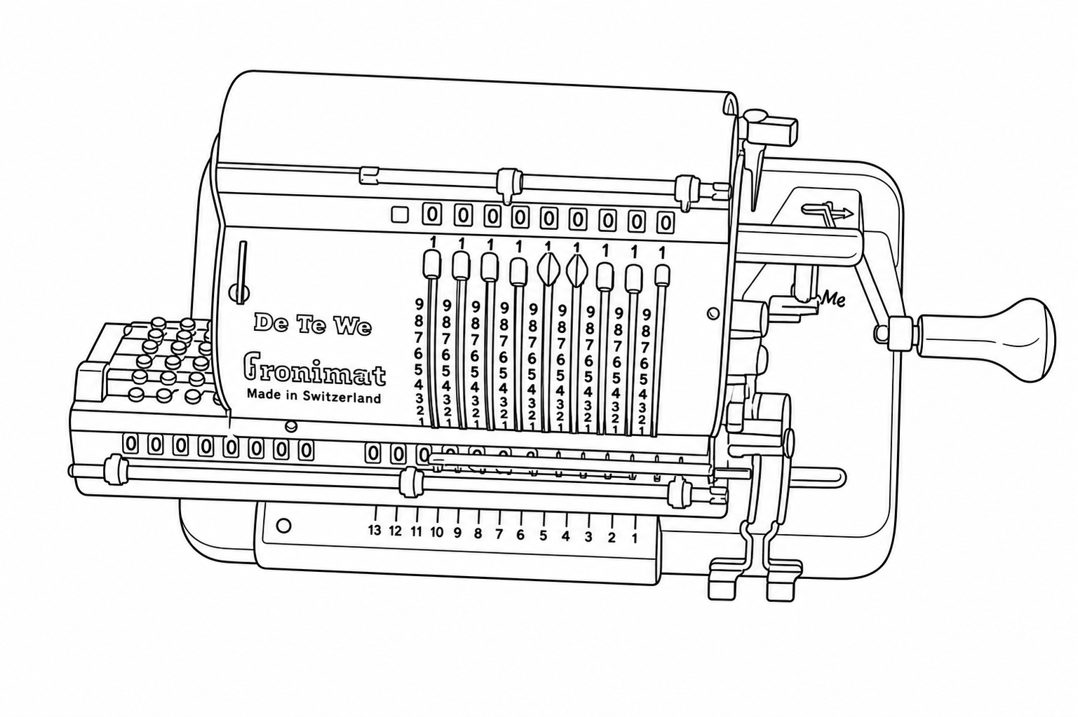
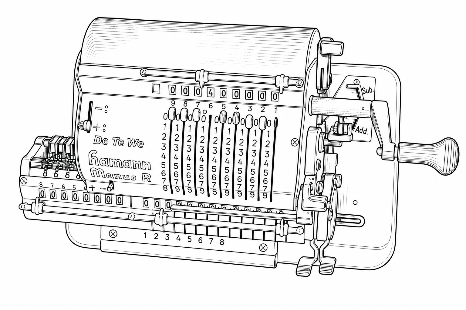
Resolution matters more than anything else. This is the single largest factor determining the quality of your generated line drawing. And it's not just that higher resolution is better in the abstract; what matters is whether the resolution is sufficient relative to the amount of detail in the image. A device like this calculator, with nine columns of single-digit numbers, fine mechanical levers, and small text, needs high pixel density to give the Sandbox enough information to work with. At 512×341, there simply aren't enough pixels per structural element for accurate reconstruction. At 1920×1280, the results are usable (but higher resolution and better lighting would be preferred).
As a rough guideline: highly detailed mechanical devices (dense text, many small components, fine tolerances between adjacent features) probably need something in the range of 2000–4000 pixels on the long edge. Simpler devices with fewer structural elements and more visual separation between them can get away with 1200 pixels or so. The question to ask yourself is: “If I zoom in on the most detailed region of this photo, can I clearly distinguish every feature I need reproduced?” If you can't, the Sandbox won't be able to either.
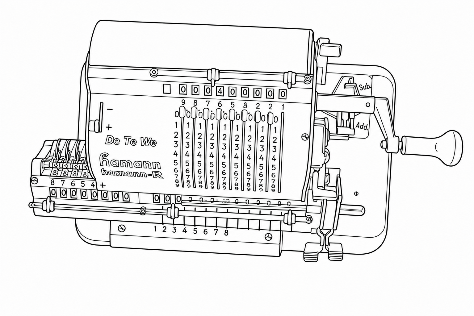
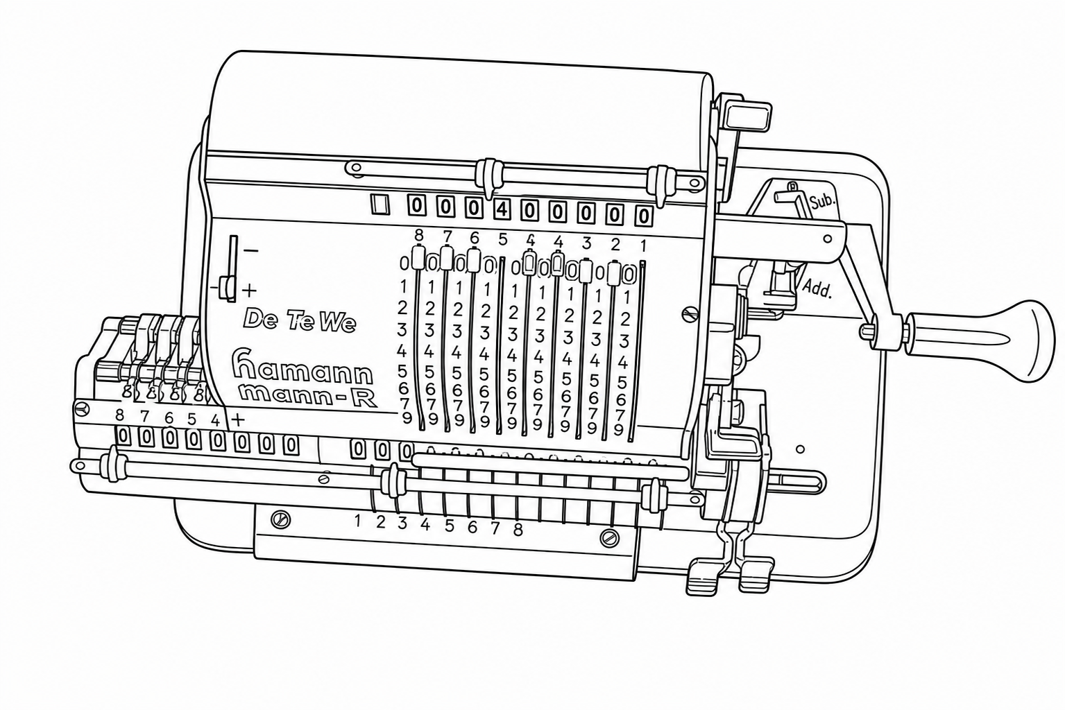
Prompt 1 performed best. The critical difference is the clause: “when a feature is hard to see or blurry, do your best to infer the likely structure based on surrounding context.” This gives the Sandbox permission to reason about what a partially-obscured feature should look like, rather than slavishly reproducing visual noise or blur as-is. Looking at the numbered columns, Prompt 1 correctly renders the rows of 8s and 9s as distinct, properly separated rows.
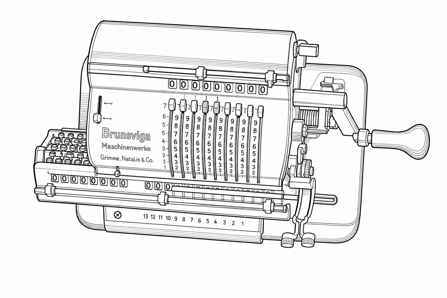
Prompt 2 produced the most systematic errors. The minimal prompt generated clean-looking line drawings, but with structural deviations from the actual device. The orientation of the device shifts slightly, and entire rows of detail get reorganized rather than faithfully reproduced. For example, the row of 8s essentially disappears, with the row of 9s partially replaced by 8s instead. These aren’t noisy artifacts; they’re confident, clean-looking wrong answers. That makes them harder to catch on visual inspection, which is arguably worse than obvious noise.
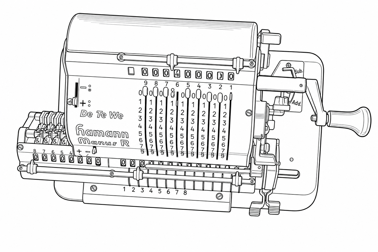
Prompt 3 produced a different kind of error: fine-detail noise. Unlike Prompt 2’s systematic rearrangements, Prompt 3’s errors show up as small-scale distortions in dense regions. The 8s start merging into the tops of the 9s, individual digits blur together, and tightly-spaced features lose their separation. The strict faithfulness instruction seems to force the Sandbox into reproducing ambiguity literally rather than resolving it intelligently. Where the image is slightly unclear, Prompt 3 renders that unclarity as visual noise rather than inferring the correct structure.
The practical lesson: start with resolution. This is the lever that matters most, and no amount of prompt engineering will compensate for an input image that doesn't have enough pixels to represent the detail you need. Once your resolution is sufficient, use a prompt that gives the Sandbox explicit permission to infer structure in ambiguous areas (like Prompt 1). A minimal prompt risks confident-but-wrong structural changes. An over-constrained prompt risks fine-detail noise in dense regions. The sweet spot is being specific about what you want (clean lines, faithful structure) while giving the Sandbox room to reason about anything that isn't perfectly clear in the source image.
Updates & Changelog
- Illustration model upgrade. The underlying model powering “Draft — Figure (Illustration)” has been updated. This improves accuracy when converting natural images to line drawings, provides better instruction following, and produces better results for de novo illustration generation from text-only prompts.
- Aspect ratio fix for illustrations. Previously, input images with non-standard aspect ratios could have their output truncated. Output images now dynamically adjust to match whatever aspect ratio is required.
-
Equation copy-paste to Word. Double-clicking an equation (or a response
bubble containing equations) and pasting into Word now inserts native Word equations
directly, no manual conversion from LaTeX required. This works for versions of
Word that support MathML. Previously, pasting would produce raw LaTeX text (e.g.,
$E=MC^2$) that required manual conversion into Word’s equation format.
If you’ve developed workflows or prompt strategies for figure illustration, or any other Sandbox mode, that you’d be willing to share in a future issue, I’d like to hear about them. — Will